
Power & Energy Solutions
Power Plant and Power Side Timing
Unified Time Source Solutions for Power Plants

DCS, protection systems, waveform recorders, telecontrol systems, and security logs all share the same time reference, enabling precise sequencing of unit operating events along a unified timeline. This is a plant-level time infrastructure designed for thermal power, hydroelectric, gas turbine, nuclear, and on-site power plants.
Challenges Associated with Time Asynchrony at Power Plants
It's not just that "the time is off"—it'sIt is impossible to reconstruct the entire sequence of events.The
A unified time source is not about “setting the server time correctly,” but rather about establishing a common time infrastructure for electrical, thermal control, automation, communications, security, and information systems.
1. DCS trends do not correspond to protection trip times
Solution for a Unified Time Source: The DCS and protection devices obtain their time from the same master clock, ensuring that electrical events and thermal processes are precisely aligned on a unified timeline.
2. Deviation Between the Fault Recording Waveform and the Protection Trip Timestamp
Solution for a Unified Time Source: The protection system and the waveform recorder obtain IRIG-B signals from the same source, ensuring that waveform analysis and protection logic are perfectly aligned.
3. Events involving multiple units cannot be sorted in a consistent order
Solution for a Unified Time Source: All units and utility systems throughout the plant share a common primary and backup clock system, making the sequence of events across units immediately clear.
4. The logs in Safety Zone III are out of sync with the time in the production zone.
Solution for a Unified Time Source: Cross-region, controlled transmission of the time reference to secondary NTP servers ensures that security audit logs across all regions are traceable to a single source.
5. The timestamps for dispatch data sent via the telecontrol system are unreliable
Solution for a Unified Time Source: The telecontrol system is directly connected to the master clock, ensuring that every data frame carries a highly accurate and reliable timestamp.
6. GNSS anomalies or primary/standby switching status are not visible
Solution for a Unified Time Source: Monitoring links are integrated throughout the entire architecture, providing real-time alerts for primary-standby switching and timing deviations, and ensuring that grid-connection acceptance testing is fully documented.
Typical Systems and Time-Synchronization Targets
Comprehensive coverage of power plant electrical secondary systems, thermal control, communications, cybersecurity, and information systems

Electrical Protection Chain

Thermal Engineering Production Chain

Audit and Operations Chain
Timeline of Unit Operating Events
The Core of Power Plant Accident Analysis: Rigorously Aligning Electrical Protection Trips with Thermal Control Process Parameters Along the Same Timeline
| Primary Source | Beidou / GNSS satellite signals, primary and backup master clocks, local rubidium clock or OCXO for time keeping | NTP / PTP | Main Data Center |
|---|---|---|---|
|
Unit Incident Review Log:
Combine protection, waveform recording, DCS, back-end systems, and telemetry data into a single engineering log, focusing on whether each entry can be verified by the same clock. |
|||
|
T0 |
Relay Protection Operation |
The IRIG-B time stamp records the trip output, serving as the starting point for the electrical event. |
Verify the sequence of the protection trip report and the SOE. |
|
T0 + 12 ms |
Fault Recorder Triggering |
COMTRADE waveforms use a common time scale to locate sudden changes in voltage and current. |
Verify that the waveform sample points match the protection operation. |
|
T0 + 2s |
DCS Trend Break |
Thermal parameters, unit load, and auxiliary equipment status are aligned according to a unified timeline. |
Determine whether the electrical system triggers first or the thermal system responds first. |
|
T0 + 5s |
Backend Alerts and Telemetry Uploads |
SCADA alarms, telecontrol data, and the timestamps received by the dispatching terminal can be cross-checked against one another. |
Prepare accident reports and grid connection evaluation materials. |
|
Abnormal Items |
Time-shifted samples |
If there is a discrepancy of one second or more in the DCS, waveform recordings, or security logs, they should be directly marked as inadmissible as standalone evidence. |
Trigger an NTP/IRIG-B link retest and a primary/standby status check. |
Recommended Overall Architecture
Time Source Layer → Master Clock Layer → Distribution Layer → Business System Layer, featuring an end-to-end online monitoring and alerting chain
End-to-End Monitoring and Alerting Chain
Uploaded to the monitoring system:
- GNSS Antenna Status
- Number of Satellites Locked On
- Current Time Source
- Switching Between Primary and Backup Roles
- On-Time Status/Out of Tolerance
- Power and Port Anomalies

Time Synchronization Design for Safety Zones
While meeting the security requirements of the power monitoring system, ensure uniform time coverage throughout the entire plant.
Time Synchronization for Safety Zones I and II
Time Synchronization in Safety Zone III
Multiple Units and Utility Systems
Compatibility with Existing Equipment
Recommended Time Synchronization Methods and Interface Matrix
Quick Selection Guide for Common Time Synchronization Interfaces Used in Power Plants
| Primary Source | Beidou / GNSS satellite signals, primary and backup master clocks, local rubidium clock or OCXO for time keeping | NTP / PTP | Main Data Center |
|---|---|---|---|
|
Protection / Waveform Recording / SOE |
From submicroseconds to milliseconds |
IRIG-B DC / 1PPS + TOD / BNC / RS-485 |
|
|
DCS / SIS / PLC |
Milliseconds to hundreds of milliseconds |
NTP / IRIG-B / Serial Messages / RJ45 |
|
|
Telecontrol / Communications / PMU |
From microseconds to hundreds of milliseconds |
IRIG-B / 1PPS + TOD / 10 MHz / E1 |
|
|
Safety Zone III |
Sub-second Log Correlation |
Level 2 NTP / SYSLOG / SNMP / RJ45 |

Primary-Standby Redundancy, BeiDou Priority, and Local Time Keeping
A power outage at a hub substation could cause widespread voltage drops downstream; as a critical infrastructure, the time synchronization system must eliminate the risk of single-point failures.
1+1 Primary-Standby Redundancy:Configure primary clock A and backup clock B, dual power supplies (from different feeders), dual GNSS antennas, and multiple network ports. Primary and backup fiber-optic links cross-check each other; in the event of a failure, the system automatically and seamlessly switches over, and the switchover time does not affect the normal operation of the protection device.
Beidou-Priority Multi-Mode:Supports BeiDou-2 and BeiDou-3; can be configured for BeiDou single-mode or multi-mode parallel reception, enhancing interference resistance.
GNSS Loss of Local Time Keeping:When satellite signal loss occurs due to thunderstorms or interference, the built-in rubidium atomic clock or OCXO seamlessly takes over to maintain time. During this period, the timestamps for protection operations, waveform recordings, SOE, and PMU data remain continuously available.
The timing system itself must be monitorable.
Alarm Escalation Methods: Support via Dry Contacts,SNMP Trap,SYSLOG or Power Industry-Specific Protocols (IEC 61850 / 104) Integrate with DCS, integrated monitoring systems, or security audit platforms. Transform the time synchronization system from an “unmonitored black box” into a manageable piece of infrastructure.
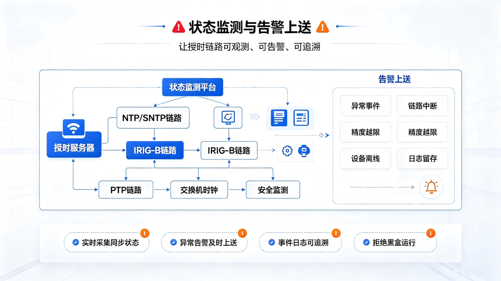
- GNSS Antenna Status (Open Circuit/Short Circuit)
- Number of Satellites Acquired and Signal Quality
- Current Time Source (Beidou/Time Keeping)
- Primary and Standby Roles and Switching Event Log
- Timekeeping Status and Timekeeping Deviation
- Port Output Abnormal Alarm
- Power Failure Alarm
- Time Shift Out-of-Limits Alarm
The Value of the Solution in a Power Plant Setting
Failure analysis is more reliable
Plant-wide protection, waveform recording, DCS, and SOE data are recorded using a unified reference, and the progression of incidents is presented along a clear timeline, eliminating disputes caused by discrepancies.
Grid-Connection Dispatch Data Is More Reliable
Data transmitted via the remote signaling system carries a trusted timestamp, supporting AGC adjustment evaluations and compliance assessments under the "Two Detailed Rules," thereby preventing unnecessary penalty points.
Precise Alignment of Electrical and Thermal Control Systems
Changes in process parameters correlate precisely with electrical trip events over time, significantly improving the efficiency of cross-disciplinary root cause analysis.
Security, Audit, Compliance, Availability
Security devices across different zones are synchronized with the logging platform, providing a reliable basis for reconstructing the attack chain and meeting the compliance audit requirements of the Grade 2.0 Information Security Certification.
Unified Sorting of Multi-Unit Incidents
Whether a single-unit failure or a problem with the utility system affects the entire plant, all records are sorted uniformly, making complex events—such as plant power switching—easy to understand at a glance.
Technical Upgrade Acceptance Is Documented
We provide comprehensive test reports covering accuracy, switching, and hold-up time, ensuring that system delivery is no longer just a matter of “seeing the light come on,” but is backed by a traceable chain of evidence for acceptance.
Implementation and Delivery Process
What we deliver is not just a single piece of equipment, but a time synchronization infrastructure that can be tested, accepted, and maintained.
Analysis of the Source of the Incident
Group events by protection, waveform recording, DCS, telecontrol, and security logs to verify their sources and accuracy requirements.
Primary-Standby Deployment
Deploy primary and backup clocks, antennas, and time-keeping units, and define the time synchronization paths for each security zone.
Critical Integration Testing
Verify the status of IRIG-B, NTP, 1PPS, serial messages, and alarm reporting on a per-item basis.
Event Chain Verification
Verify source-to-source time consistency using protection operations, DCS trends, and waveform data.
Operations and Maintenance Integration
Submit the event chain test report, the primary-to-standby switchover log, and the time system inspection specifications.
Frequently Asked Questions
Why does a power plant’s DCS system need to be synchronized with the protection systems?
Protection trips on the electrical side of a power plant are often causally linked to changes in DCS process parameters on the thermal control side. If there is a time discrepancy between the DCS and the protection system (ranging from tens of milliseconds to several seconds), it is impossible to determine during fault analysis whether “the protection tripped due to electrical parameters exceeding limits or because of abnormal thermal parameters.” A unified time reference aligns electrical events and thermal trends on a single timeline, providing an indisputable chain of temporal evidence for root cause analysis.
How can the schedules of multiple units be managed in a unified manner?
A redundant master clock system (Master Clock A + Standby Clock B) is deployed at the master clock level, with each unit and the plant-wide systems obtaining their time reference from the master clock via fiber-optic cables or the network. Protection, waveform recording, DCS, and telemetry equipment on each unit access the unified time via IRIG-B (Safety Zones I and II) or NTP (Safety Zone III), ensuring that events across the entire plant can be sequenced uniformly. Each unit’s control room can be configured with an independent expansion unit that obtains the time from the master clock and distributes it within the unit’s scope, thereby maintaining regional independence while ensuring a unified source.
How does Safety Zone I (MIS/SIS) at a power plant obtain a trusted time source?
A physical isolation device exists between Security Zone III and Security Zones I/II. By deploying an independent secondary NTP time server in Security Zone III—which obtains its time reference from the master clock in Security Zones I/II via the isolation device—NTP time services can be distributed to the MIS, SIS, log auditing platform, and security devices. This approach meets the lateral isolation requirements for the security protection of power monitoring systems while ensuring that the time source is consistent across the entire plant.
What test records are required for time synchronization during the grid connection acceptance inspection of a power plant?
It is recommended to provide: test records for primary/backup clock switching; test data on time-keeping accuracy after GNSS loss; a confirmation table of the time synchronization status for each time-synchronized device; verification records covering all port outputs; and test records for alarm interlocking. Comprehensive test records elevate acceptance testing from merely “checking that lights are on” to a process based on “verifiable data and traceability,” while also serving as a baseline for subsequent operations, maintenance, and inspection activities.
Obtain a Plan for Synchronizing the Unified Time at Power Plants
Please submit your unit configuration, list of time-synchronized devices, and security zone information, and we will provide tailored design and configuration recommendations for your power plant’s time synchronization solution.
When submitting the list, it is recommended that you include:
- Project Type (New Construction/Technological Upgrades/Expansion)
- Number and Type of Units
- Types and number of devices that require time synchronization
- Available Time Synchronization Interface Types
- Is Beidou required to be given priority?
- Does this involve security zones and cross-zone time synchronization?


 简体中文
简体中文  English