
Power & Energy Solutions
Substation time harmonization system
Substations / Step-up Stations Time Synchronization Solutions

A unified time reference across the station control layer, bay layer, and process layer, covering all time-synchronization targets throughout the station, including protection, measurement and control, waveform recording, SOE, PMU, and telecontrol.
Challenges in Time Synchronization for Substations
The most challenging aspect of accident analysis is not a lack of data, but rather that the data does not match up. Substations require a unified time infrastructure that covers all levels and interface types throughout the entire facility.
1. Time Deviation Between Protective Devices and Fault Recorders
There is a deviation of several tens of milliseconds between the protection trip time and the time stamps on the COMTRADE file waveforms, making it impossible to determine whether the recorded waveforms correspond to the protection trip time. This directly affects fault location and the evaluation of protection behavior.
Solutions:The protection and waveform recording systems obtain IRIG-B DC signals from the same source, ensuring that each sample point in the waveform corresponds precisely to the protection trip time.
2. The SOE event timestamps are inaccurate, and the sequence of switch position changes is unclear.
Time-stamp deviations in switch position events recorded by the SOE unit cause the bus-to-bus tie switch position to be recorded after the line switch, leading to the assessment of fault isolation scope and protection coordination logic relying on “empirical inferences,” which may result in incorrect conclusions.
Solutions:The SOE obtains a unified time reference via IRIG-B, with event timestamps accurate to the millisecond; the sequence of switch position changes strictly corresponds to the physical process.
3. Time discrepancies between the measurement and control system, the monitoring backend, and the telecontrol unit
The same event appears at three different times in the measurement, control, and remote signaling systems, backend alarms, and data uploaded via the telecontrol system. As a result, the dispatch center is unable to construct a unified event sequence for the entire network, which affects incident reconstruction and substation operational evaluation.
Solutions:The station control level, bay level, and telecontrol channels obtain time from the same master clock, and the dispatch data they send upward carries a time stamp from the same source.
4. GNSS anomalies or loss of visibility during primary-backup switching
When the antenna is damaged or the signal is blocked, the system automatically switches to time-keeping mode without issuing any alerts; it is not until several weeks later that it is discovered that the protection device’s time stamps have drifted significantly—the time system has become a “black box,” and all time stamps during the period of latent failure are unreliable.
Solutions:GNSS status, remaining time-keeping capacity, primary/standby roles, and port output status are transmitted in real time to the monitoring backend; the system proactively issues alerts in case of anomalies and prevents “black box” operation.
Hierarchical Devices and Time-Synchronization Targets
Covers all types of equipment at the station control, bay, and process levels, providing multi-protocol time synchronization solutions compatible with conventional substations, smart substations, and retrofitted substations.

Station Control Level
Service monitoring backends, SCADA systems, telecontrol devices, communication gateways, signal acquisition substations, and log auditing systems—with a focus on ensuring a unified timestamp for alarms, remote signals, and operations and maintenance logs.

Spacer Layer
Supports protection, measurement and control, fault recording, SOE, and PMU, with a focus on ensuring that protection operations, switch positions, and recorded waveforms can be replayed on the same timeline.

Process Layer
Supports smart terminals, combined units, and process-layer switches, with a focus on ensuring SV sampling, GOOSE tripping, and process-layer network synchronization at smart substations.
Station Control Layer / Bay Layer / Process Layer Time Synchronization Board
The substation page organizes information into a three-tier structure within the station: each tier covers different equipment, protocols, and key acceptance criteria, avoiding the simplification of the entire station into a single list of NTP devices.
Station Control Level
For monitoring backends, telecontrol systems, communication gateways, and log auditing, the focus is on ensuring consistent timestamps when alerts are generated and data is uploaded via telecontrol.
Spacer Layer
For protection, measurement and control, waveform recording, SOE, and PMU, the focus is on ensuring that protection operations and recorded waveforms correspond precisely.
Process Layer
Designed for smart terminals, aggregation units, and process-layer switches, this solution focuses on ensuring synchronization of sampling and trip messages at smart substations.
Solution Architecture
A four-tier architecture design with independent monitoring links, covering equipment at all levels throughout the station—including the station control layer, bay layer, and process layer.

End-to-End Monitoring and Alerting Chain
Hard Contacts / SNMP / SYSLOG / 104 / 61850:
- GNSS Antenna Status
- Number of Satellites Locked On
- Current Time Source
- Record of Primary-Standby Role Switches
- Timing Status / Out-of-Tolerance Alert
- Port Output Status
- Power Supply Status Monitoring
Partitioning and Hierarchical Timing Design
Station Control Level Time Synchronization (NTP/SNTP)
Interval-Based Time Synchronization (IRIG-B)
Process Time Protocol (PTP)
Time Synchronization for New Energy Substations
Compatibility Between Existing Stations and Technologically Upgraded Stations
Interface Matrix (Simplified Version)
Station Control Level
The monitoring backend, telemetry system, switches, security devices, and Baoxin substations use network-based time synchronization to ensure consistent timestamps for alarms, logs, and dispatch data.
Spacer Layer
Protection, measurement and control, waveform recording, SOE, and PMU—hardware timecode is used to ensure a precise correspondence between protection operations and recorded waveforms.
Process Layer
Smart terminals, aggregation units, and process-layer switches rely on high-precision network clocks to ensure SV sampling and GOOSE time stamps.
Value of the Solution
The accident analysis is well-documented.
Site-wide protection and standardized SOE records ensure that the sequence of protective actions aligns with the physical process, eliminating the need for empirical inferences.
Proactive System Status Monitoring
GNSS status, timing accuracy, and primary/backup roles are transmitted in real time to the monitoring backend, shifting the system from "passive detection" to "active sensing."
Unified Alignment of Waveform Recording and PMU Data
Each cycle of the recorded waveform corresponds precisely to the time of protection operation, and the PMU phase angle data is linked to the event sequence, making in-depth analysis more reliable.
Grid Connection Acceptance Closed-Loop Process
Primary-standby switching, timing maintenance, and port verification generate traceable records; a comprehensive test report is provided to support the closed-loop grid connection acceptance process.
Reliable timestamp reporting to the dispatcher
Telemetry devices operate in unison, and the data transmitted to the dispatch master station carries a reliable, consistent time stamp, supporting grid-level fault analysis and operational evaluation.
Compatibility with New and Old Equipment
It simultaneously outputs IRIG-B, NTP, serial ports, and pulses, allowing both existing and newly installed smart devices to select the options that best suit their needs, thereby protecting existing investments.

Primary-Standby Redundancy, BeiDou Priority, and Local Time Keeping
A power outage at a hub substation could cause widespread voltage drops downstream; as a critical infrastructure, the time synchronization system must eliminate the risk of single-point failures.
1+1 Primary-Standby Redundancy:Configure primary clock A and backup clock B, dual power supplies (from different feeders), dual GNSS antennas, and multiple network ports. Primary and backup fiber-optic links cross-check each other; in the event of a failure, the system automatically and seamlessly switches over, and the switchover time does not affect the normal operation of the protection device.
Beidou-Priority Multi-Mode:Supports BeiDou-2 and BeiDou-3; can be configured for BeiDou single-mode or multi-mode parallel reception, enhancing interference resistance.
GNSS Loss of Local Time Keeping:When satellite signal loss occurs due to thunderstorms or interference, the built-in rubidium atomic clock or OCXO seamlessly takes over to maintain time. During this period, the timestamps for protection operations, waveform recordings, SOE, and PMU data remain continuously available.
Status Monitoring and Alarm Reporting (Rejecting "Black Box" Operation)
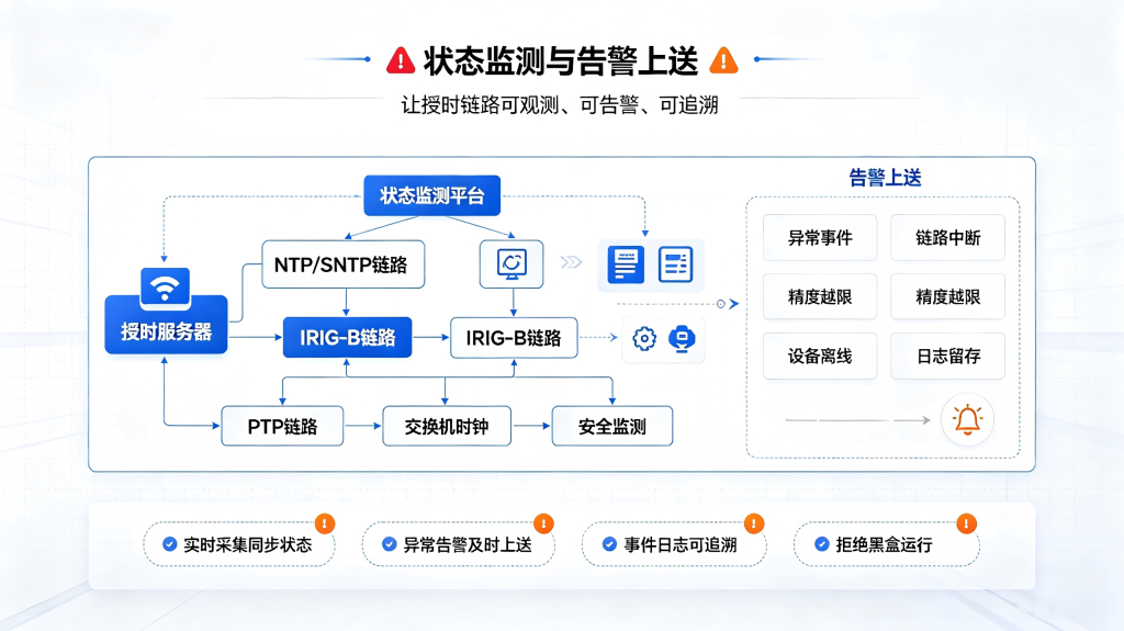
Alarm Escalation Methods:support Dry Contacts,SNMP Trap,SYSLOG,DL/T 634.5104 or IEC 61850. Incorporate the status of the time system into the site's daily monitoring and operations and maintenance system.
- GNSS Antenna Status (Open Circuit/Short Circuit)
- Number of Satellites Acquired and Signal Quality
- Current Time Source (Beidou/Time Keeping)
- Primary and Standby Roles and Switching Event Log
- Timekeeping Status and Timekeeping Deviation Alerts
- Port Output Abnormal Interrupt
- Power Failure
- Time Step Exceeds Limit
Implementation and Delivery Process
What we deliver is not just a single piece of equipment, but a time synchronization infrastructure that can be tested, accepted, and maintained.
Tiered Analysis
Verify the equipment, interfaces, accuracy, and relay room locations by station control level, bay level, and process level.
Primary-Standby Deployment
Complete the configuration of the primary and backup clocks, antennas, lightning protection, dual power supplies, and time-keeping capabilities.
Substation Control Integration
Connect to the monitoring backend, TIA, communication gateway, and logging system to verify the NTP status.
Interval Verification
Verify the consistency of the IRIG-B output, protection operation timestamps, SOEs, and waveform recordings for each screen cabinet.
Process Validation
Conduct high-precision verification of smart terminals, aggregated units, and PTP networks, and generate a report.
Frequently Asked Questions
Why do SOEs (Sequence of Events) in substations have such strict requirements for time synchronization?
The core function of an SOE device is to record switch position changes and protection operation events in chronological order. If the time synchronization deviation exceeds the SOE’s resolution requirements (typically 1 ms or higher), the sequence of switch operations may be recorded incorrectly—which directly affects the determination of whether “the protection operated correctly or the circuit breaker itself failed.” Time synchronization in substations typically requires the IRIG-B DC code (with microsecond-level precision) to be fed into the SOE unit, ensuring that the chronological order of recorded events perfectly matches the physical sequence of events.
What is the difference between smart substations and conventional substations in terms of time synchronization?
Conventional substations primarily use IRIG-B and serial messages, with bay-level devices connected via cables, resulting in a relatively simple time synchronization architecture. Smart substations incorporate process-layer consolidation units and intelligent terminals, requiring networked, high-precision time synchronization via PTP (IEEE 1588v2). The solution must address both requirements simultaneously—maintaining IRIG-B/serial port compatibility with existing conventional equipment while providing PTP support for the process layer of smart substations, thereby ensuring that new and legacy equipment operate in coordination under a common time reference.
What are the consequences of an IRIG-B synchronization interruption in a substation protection system?
Protection devices typically have the ability to maintain their internal clock for a short period (usually several hours), but if an IRIG-B interruption lasts longer than a certain duration, the time stamp of the protection event will gradually drift. In complex faults involving coordinated multi-level protection, timestamp deviations may lead to ambiguities in the analysis of protection operation sequences—for example, making it impossible to determine whether the primary or backup protection operated first. Therefore, the solution emphasizes primary-backup clock redundancy, local time-keeping in the event of GNSS loss, and monitoring of port output status to ensure the continuity and reliability of the IRIG-B signal.
What are the requirements for the time stamp when data is sent from a substation's telecontrol system to the dispatch master station?
The dispatch control center requires that the remote signaling, telemetry, and SOE data transmitted from substations include accurate timestamps for use in grid-wide state estimation, fault analysis, and AGC control. If the time on the telecontrol device does not match that of the dispatch control center, the sequence of switch positions observed by the dispatcher may not correspond to the actual sequence, which could in turn affect fault diagnosis and response decisions. This solution provides a unified time reference for the telecontrol units via NTP or IRIG-B, ensuring that the timestamps of the uploaded data are synchronized with those of other equipment within the substation.
Obtain a Time Synchronization Solution for Substations
Whether you’re facing technical upgrades to an existing substation, grid connection acceptance testing for a new smart substation, or the construction of a new energy step-up substation, Beidou Bangtai’s engineering experts are always ready to provide professional advice. We help you build a robust time infrastructure that spans the substation control layer, bay layer, and process layer, ensuring that all substation events are recorded on a single timeline.
When submitting the list, it is recommended that you include:
- Voltage Levels and Types of Substations
- Types and Quantities of Spacer Equipment
- Available Time Synchronization Interfaces (IRIG-B/NTP/Serial)
- Does this involve the process layer of the smart substation?
- Is it necessary to synchronize the time with the main dispatch station?


 简体中文
简体中文  English